Reversing a Remote Controller: A Case Study in RF Engineering
Feeling bored, I decided to take on a personal challenge: reverse-engineer a toy’s remote controller. My goal was to gain practical experience with radio communication and create a custom controller with new features, like controlling it remotely over Wi-Fi. It’s a classic hands-on project that starts with a simple question: what makes this thing tick?
Exploring the Target Device
I had a toy with a remote controller laying around. The remote controller has 3 buttons for 3 different functions: power, change the rhythm of the bottom part, change the rhythm of the top part. I was suspecting that the remote controller uses radio waves to communicate with the toy like other similar remote controllers.
After opening the remote controller, My suspicion was confirmed.
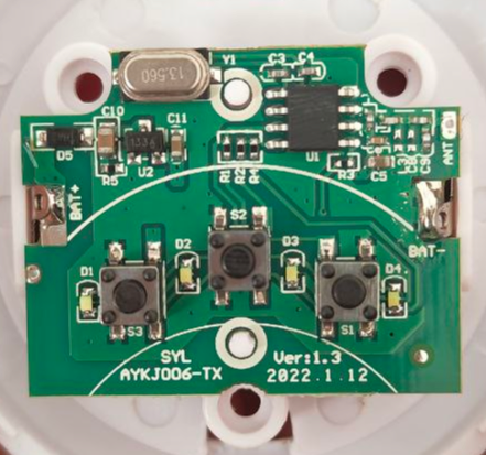
A few things immediately jumped out that pointed toward a specific frequency. The board is labeled AYKJ006-TX, with TX being the standard abbreviation for a transmitter. More importantly, the distinct, curvy copper line labeled ANT is clearly a PCB trace antenna. Simple, short-range remotes like this almost always operate in the unlicensed ISM bands, with 433 MHz being one of the most common frequencies worldwide. This made 433 MHz my primary suspect.
Let’s look at the components.
-
The Encoder and Transmitter IC (
U1)The most important component on this board is the large black chip labeled
U1. It has 2 primary functions:
- Encoder: When user presses a button, it converts that action into a command.
- Transmitter: After generating the command, the chip modulates it onto a 433 MHz radio frequency carrier wave.
-
The Crystal Oscillator (
Y1)The shiny, metallic component labeled
Y1is a crystal oscillator. It generates a stable clock signal that is used by the main chip (U1).If you look closely, you will notice it’s marked “13.560,” which means it vibrates at 13.560 MHz and not 433 MHz. This is a common engineering trick. The main chip (
U1) contains a circuit called aPhase-Locked Loop (PLL), which acts as a frequency multiplier. It takes the stable 13.560 MHz signal and multiplies it by 32 to generate the final transmission frequency:13.560MHz × 32 = 433.92 MHzIt’s often cheaper and more stable to use a lower-frequency crystal and multiply it up.
-
The User Interface Components
There are 3 buttons for 3 different functions: power, change the rhythm of the bottom part, change the rhythm of the top part labeled as
S1,S2, andS3. Also there are 4 different LEDs labeled asD1,D2,D3, andD4. They provide a visual feedback when the button is pressed. -
Power Management Components
- Battery Terminals (
BAT+/BAT-): These are the metal contacts where the battery (CR2032) is connected to power the entire circuit. - Voltage Regulator (
U2): Its job is to take the variable battery voltage and provide a constant, clean voltage (3.3V) that the main chip (U1) needs to operate on.
Planning the Next Steps
My goal was to reverse engineer the remote controller and create a custom one that can control the device. I needed to understand the communication protocol used by the remote controller to be able to replicate those signals. To achieve this, I had 2 options:
- Using a Logic Analyzer: A logic analyzer is a tool that captures and displays digital signals within an electronic circuit. To use this method, I would have had to solder tiny wires directly to the pins of the encoder chip (
U1). This would let me “eavesdrop” on the exact digital commands the chip generates when a button is pressed, before they are turned into a radio wave.-
Pros: It provides a very clean, noise-free look at the digital data.
-
Cons: It requires delicate soldering skills, risks damaging the board, and tells you nothing about the radio transmission part of the signal (the modulation).
-
- Using a Software Defined Radio (SDR): An SDR is essentially a radio scanner for a computer. It’s a device that can be tuned to almost any frequency to receive raw radio signals directly from the air. I could use it to capture the exact 433 MHz signal the remote sends out, just as the toy’s receiver would hear it.
-
Pros: It requires no physical modification to the remote. It captures the complete, final signal as it’s transmitted.
-
Cons: The captured signal can have noise from other radio sources, and it requires software on a computer to process and decode the raw radio data back into a digital command.
-
Since I had an SDR device lying around and wanted a practical project to learn more about radio hacking, I decided to go with option 2.
Capturing the Radio Waves
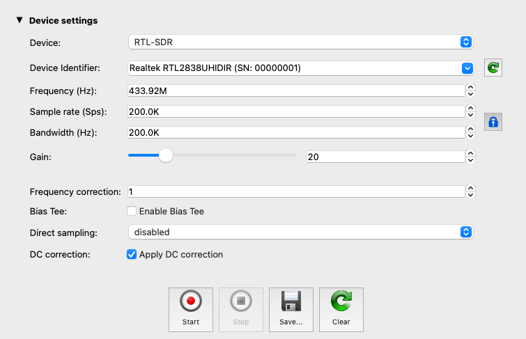
To capture the radio waves, I plugged my RTL-SDR device into my computer and used a software suite called Universal Radio Hacker (URH).
The Universal Radio Hacker (URH) is a complete suite for wireless protocol investigation with native support for many common Software Defined Radios.
With the software running, I configured my setup to get the cleanest signal possible:
- I tuned the SDR to the frequency of the remote (433 MHz).
- Next, I adjusted the gain. Since the remote was right next to the SDR’s antenna, the signal was very strong. A high gain would only amplify unnecessary background noise, so I lowered it significantly.
- Then, I created a ground plane to improve reception. For the simple monopole antenna that comes with most SDRs, placing it on a metal plate (or any large metal surface) acts as a ground plane, which helps stabilize the signal and reduce interference.
- Finally, I hit the record button in URH to start capturing.
Voila! I had a clean, noise-free sample of the transmission. Now I could jump into the next part.
Probing for a Rolling Code
With everything ready, I began transmitting. The button for the toy’s top part (S1) cycles through four different rhythm modes. To capture the full sequence and check for consistency, I pressed the button eight times, ensuring I recorded two full cycles of all four modes.
There was a critical reason for this repetition. I needed to check if the protocol had any “moving parts,” like a rolling code or a timestamp. More secure systems, like car key fobs, change the code with every press to make replay attacks impossible. By capturing two sets of signals for each of the four modes, I could compare them. If the first signal for “mode 1” was identical to the second signal for “mode 1,” it would mean the code is static, and a simple replay attack would likely work.
This was a make-or-break step. If the code wasn’t static, I’d have to figure out how to generate the new code for each transmission. That would likely mean reverse-engineering the U1 chip itself, and an SDR isn’t the right tool for that kind of task.
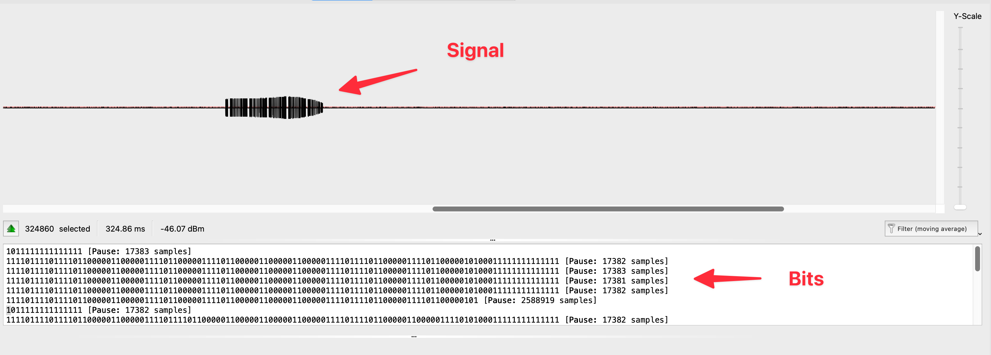
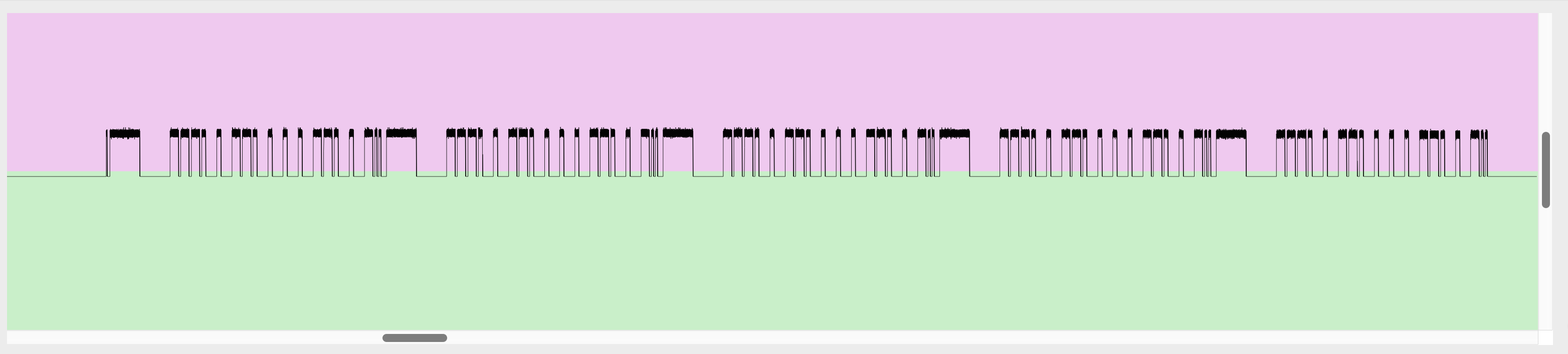
URH attempts to automatically analyze the signal and show the bits. In my case, its interpretation wasn’t perfect, but it didn’t need to be. It was clear enough to see that the payload was static. After each cycle, it sent the exact same payload for that mode.
As you can see, in the following image, searching for the single pattern resulted in 2 different groups of matches.
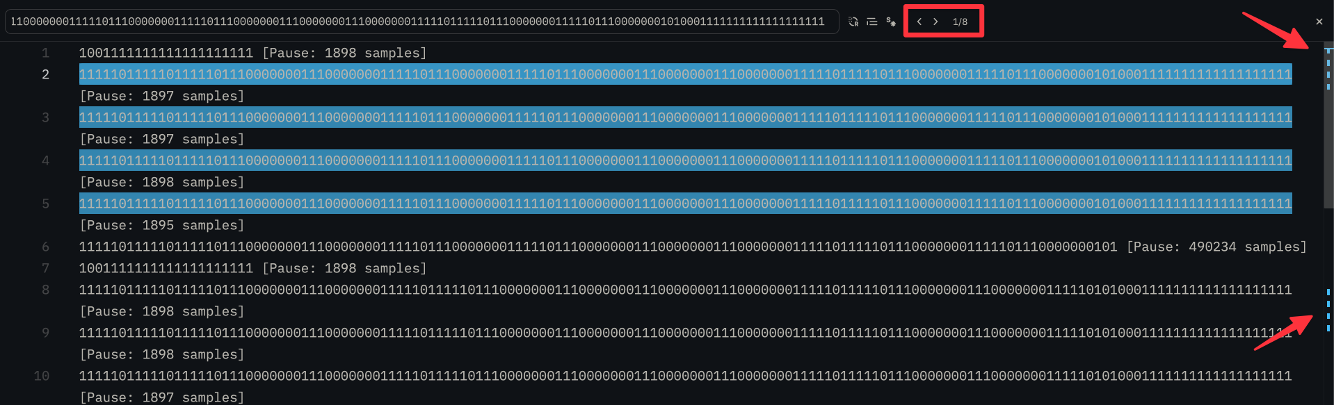
That was the confirmation I needed. The device uses a static code, which means it’s completely vulnerable to a replay attack. Game on.
A Quick Note on Security: It’s worth pointing out that finding a “vulnerability” like this in a simple toy isn’t an indictment of the manufacturer. Implementing secure rolling codes (cryptography) adds complexity and cost. For low-cost consumer electronics, manufacturers make a deliberate trade-off, opting for simple, static codes that are cheap and reliable over robust security. This is expected and perfectly normal for this class of device.
Demodulating the Signal
In simple terms, modulation is the process of encoding digital data (our ones and zeros) onto a radio wave, and demodulation is getting that data back off the wave at the other end.
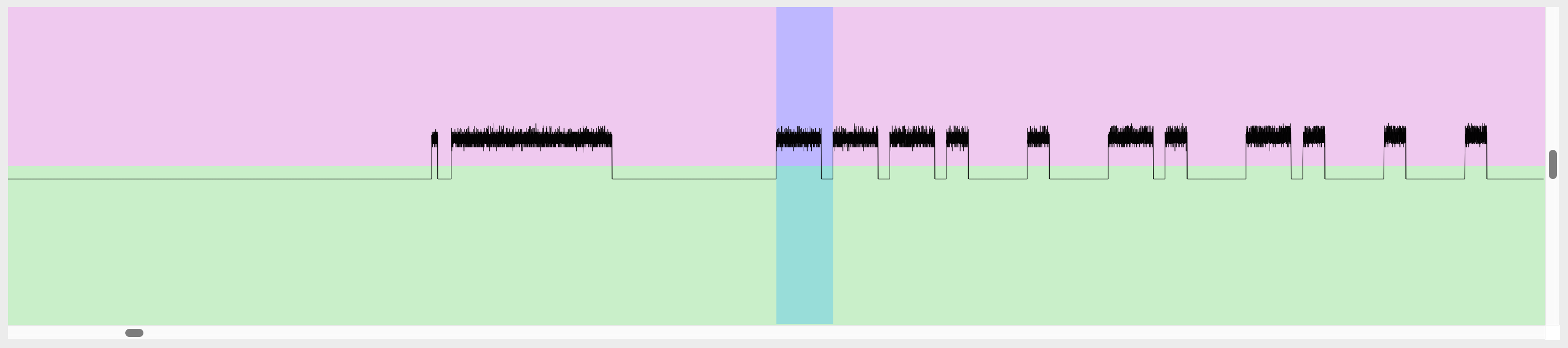
Figuring out the modulation type was straightforward once I looked at the captured signal. The pattern was a dead giveaway for Amplitude Shift Keying (ASK), one of the simplest forms of digital modulation.
The key thing to look for with ASK is the “on-off” nature of the transmission. When I viewed the signal in URH, I didn’t see a continuous wave that changed its shape. Instead, I saw a series of clean, distinct bursts of radio energy separated by total silence. This is the classic signature of ASK, meaning the transmitter sends a 1 by turning the 433 MHz carrier wave ON (high amplitude) and sends a 0 by turning it OFF (low amplitude, or silence).
But how does it know how long each 1 or 0 should be? That’s where the encoding scheme comes in.
What is a PWM?
The specific method this remote uses to structure its ones and zeros is a form of Pulse Width Modulation (PWM). Don’t let the name intimidate you; the concept is really simple. It uses pulses of different lengths (or widths) to represent different data.
Think of it like sending a message with a flashlight in the dark:
- To send a 1, you might do a long flash followed by a short pause.
- To send a 0, you’d do a short flash followed by a long pause.
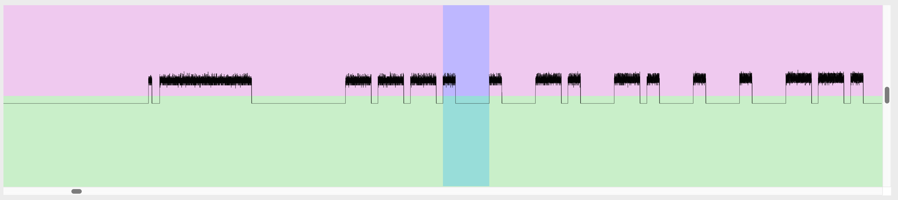
The receiver on the other end just has to measure the duration of each flash and each pause to reconstruct the original message. My remote does the exact same thing, just with radio waves instead of light and with timings measured in microseconds. By analyzing the captured signal, I could see two distinct pulse lengths, a short one and a long one, confirming that this was the method being used.
Dissecting a Command
With the encoding method figured out, I could finally dissect a complete command. My first step was to lean on URH’s built-in analysis tools, which gave me a bird’s-eye view of the entire transmission structure.
A single press of a button wasn’t just one command; it was a whole conversation. The remote was clearly designed for reliability, sending its message multiple times to make sure the toy heard it correctly. The structure for every button press was identical:
1001111111111111111111 [Pause: 1898 samples]
111110111110111110111000000011100000001111101110000000111110111000000011100000001110000000111110111110111000000011111011100000001010001111111111111111111 [Pause: 1897 samples]
111110111110111110111000000011100000001111101110000000111110111000000011100000001110000000111110111110111000000011111011100000001010001111111111111111111 [Pause: 1897 samples]
111110111110111110111000000011100000001111101110000000111110111000000011100000001110000000111110111110111000000011111011100000001010001111111111111111111 [Pause: 1898 samples]
111110111110111110111000000011100000001111101110000000111110111000000011100000001110000000111110111110111000000011111011100000001010001111111111111111111 [Pause: 1895 samples]
11111011111011111011100000001110000000111110111000000011111011100000001110000000111000000011111011111011100000001111101110000000101 [Pause: 490234 samples]
- The Preamble: A short, distinct initial pulse. This acts like a
wake-upcall for the receiver, letting it know a real command is about to follow and allowing it to synchronize its clock.
1001111111111111111111 [Pause: 1898 samples]
- The Command Repeats: The main data payload was sent back-to-back four times. This is a common strategy in simple RF devices. If the first transmission is garbled by interference, the receiver has more chances to get a clean copy.
111110111110111110111000000011100000001111101110000000111110111000000011100000001110000000111110111110111000000011111011100000001010001111111111111111111 [Pause: 1897 samples]
111110111110111110111000000011100000001111101110000000111110111000000011100000001110000000111110111110111000000011111011100000001010001111111111111111111 [Pause: 1897 samples]
111110111110111110111000000011100000001111101110000000111110111000000011100000001110000000111110111110111000000011111011100000001010001111111111111111111 [Pause: 1898 samples]
111110111110111110111000000011100000001111101110000000111110111000000011100000001110000000111110111110111000000011111011100000001010001111111111111111111 [Pause: 1895 samples]
- The Trimmed Packet: The transmission ended with a final, shorter burst of data. This was a truncated version of the main command, likely acting as a
message oversignal.
11111011111011111011100000001110000000111110111000000011111011100000001110000000111000000011111011111011100000001111101110000000101 [Pause: 490234 samples]
With the overall structure understood, I could focus on one of those identical, repeated blocks. By analyzing the repeating patterns of high (1) and low (0) samples, I could deduce the encoding “alphabet” for a single bit of data:
-
Logical 1: A long high pulse followed by a short low pulse. In the sampled data, this corresponds to the pattern
111110. -
Logical 0: A short high pulse followed by a long low pulse. In the sampled data, this corresponds to the pattern
1110000000.
With these rules, I could now decode the full data payload. For example, applying these rules to one of the captured packets for the “top part” function gave me the 16-bit binary message:
1110 0101 0001 1010
By doing this for all the captured modes, a clear pattern emerged.
The Final Command Format
The command is a 16-bit (2-byte) packet with a clear and simple structure.
[ Address Nibble (4 bits) | Command Nibble (4 bits) | Checksum (8 bits) ]
-
Address Nibble: A 4-bit chunk that acts as a group identifier. For example, all commands for the “top part” used the address
1110 (Hex: 0xE). This tells the receiver which function to modify. -
Command Nibble: The next 4-bit chunk is the actual instruction. For the “top part,” this value changed for each of the four rhythm modes, telling the receiver which specific pattern to activate.
-
Checksum: The final 8 bits are a simple checksum. It’s a bitwise NOT of the first 8 bits (the address and command combined). Every 1 is flipped to a 0, and every 0 is flipped to a 1. This is a computationally cheap way for the receiver to verify that it received the message without errors.
Here is a breakdown of the example command we decoded (1110010100011010):
| Part | Binary | Hex | Meaning |
|---|---|---|---|
| Address Nibble | 1110 |
0xE |
Address for the “top part” function |
| Command Nibble | 0101 |
0x5 |
Instruction for a specific rhythm mode |
| Full Byte 1 | 11100101 |
0xE5 The complete command byte |
|
| Checksum | 00011010 |
0x1A The bitwise NOT of 0xE5, used to verify the message |
Timing is Everything!
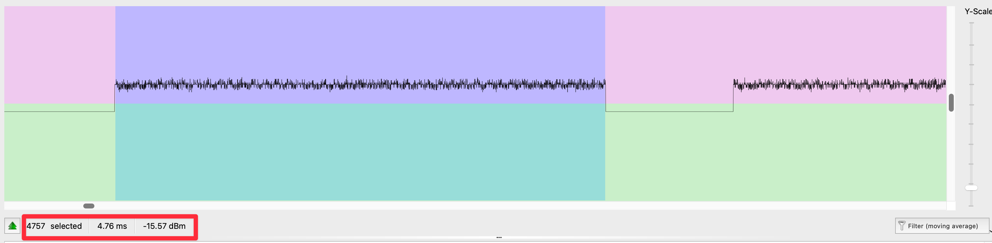
Knowing the sequence of ones and zeros is only half the job. To build a perfect clone, I had to replicate the signal’s timing with microsecond precision. A radio receiver is incredibly picky; if your pulses are too long or too short, it will reject the command as noise.
While a logic analyzer is the ideal tool for getting perfect, noise-free timing measurements directly from the hardware, it’s possible to get a very good estimate from a clean radio capture in URH. By zooming in on the demodulated signal, you can measure the number of “samples” for each pulse and pause. By establishing a base time unit (e.g., one sample equals ~5µs at a sample rate of 200k), you can calculate the approximate duration of each part of the signal.
Time per sample = 1 / Sample Rate
1 / 200,000 = 0.000005s or 5µs
This method requires some trial and error. I started with the calculated estimates and then “hand-tuned” the microsecond values in my code, testing each time until the device responded reliably.
Creating a Custom Remote Controller
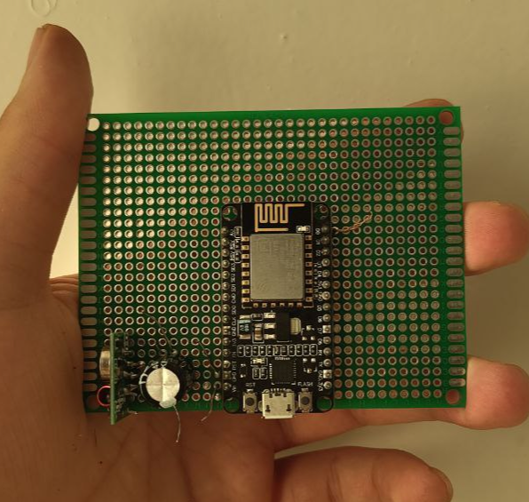
With the protocol fully reverse-engineered, the next step was to build the hardware. The goal was to create a new remote from scratch that could replicate the toy’s signals.
For the main controller, I chose a NodeMCU ESP8266 board. It’s inexpensiveyet powerful (and also has a built-in WiFi module), which is great for this kind of hardware project. For the transmitter, I used a standard 433 MHz ASK module, the same type found in the original remote.
Finally, a crucial component was a decoupling capacitor. During early tests, I discovered the transmitter’s power draw was causing signal instability. Adding a capacitor directly across the transmitter’s power pins provides the instant current needed for clean, strong pulses.
I soldered all components onto a piece of perfboard to create a compact and sturdy device. The NodeMCU is the main board, with the transmitter and its supporting capacitor placed nearby.
The final step was to translate our findings into C++ code for the NodeMCU. This involved creating functions to precisely replicate the signal’s unique structure.
The Building Blocks: Timing is Key
The foundation of the code is built on generating pulses with microsecond accuracy. The delayMicroseconds() function is perfect for this, but to ensure perfect stability and prevent timing jitter from the microcontroller’s background tasks, each pulse is sent inside a “critical section” by temporarily disabling interrupts.
The core of the signal is the PWM “alphabet” we discovered, which defines a logical 1 and a 0. The timings were hardcoded directly from our analysis:
// Timings in microseconds
const int PULSE_SHORT_US = 250;
const int PULSE_LONG_US = 520;
const int PAUSE_SHORT_US = 40;
const int PAUSE_LONG_US = 680;

void send_logical_1() {
  // A long HIGH pulse followed by a short LOW pause
  send_high_pulse_critical(PULSE_LONG_US);
  delayMicroseconds(PAUSE_SHORT_US);
}

void send_logical_0() {
  // A short HIGH pulse followed by a long LOW pause
  send_high_pulse_critical(PULSE_SHORT_US);
  delayMicroseconds(PAUSE_LONG_US);
}
Assembling the Full Command
With the functions for sending a 1 and a 0 defined, the full command structure could be built. Each transmission starts with a unique preamble, which acts as a “wake-up” call for the receiver.
// Preamble timings in microseconds
const int PREAMBLE_PULSE_1_US = 70;
const int PREAMBLE_PAUSE_US = 160;
const int PREAMBLE_PULSE_2_US = 1860;

void send_preamble() {
  send_high_pulse_critical(PREAMBLE_PULSE_1_US);
  delayMicroseconds(PREAMBLE_PAUSE_US);
  send_high_pulse_critical(PREAMBLE_PULSE_2_US);
}
Finally, the main function assembles the full 16-bit packet. It takes the 4-bit address and the 4-bit command, combines them into a single byte, and calculates the checksum by performing a bitwise NOT. It then sends the full sequence: the preamble, four full repetitions of the data packet with its trailer, and a final trimmed packet.
void send_command() {
  // Hardcoded for one of the "top part" rhythm modes
  byte address_nibble = 0b1110; // Address for the "top part"
  byte command_nibble = 0b0110; // Command for a specific mode

  // Construct the full 8-bit command
  byte byte1 = (address_nibble << 4) | command_nibble;
  // Calculate the checksum
  byte checksum = ~byte1;

  // Send the preamble once
  send_preamble();
  delayMicroseconds(PAUSE_INTER_PACKET_US);

  // Send the command + checksum + trailer 4 times
  for (int i = 0; i < REPETITIONS; i++) {
    send_byte(byte1);
    send_byte(checksum);
    send_trailer();
    delayMicroseconds(PAUSE_INTER_PACKET_US);
  }

  // Send the final trimmed packet (command + checksum only)
  send_byte(byte1);
  send_byte(checksum);
}
After uploading the code and powering it on, it worked flawlessly. The custom-built remote could control the toy’s functions just like the original, now functioning as a platform for future expansion.
I did the same thing for the other 2 buttons as well and created a fully functional replica.
Conclusion
This project was more than just building a new remote; it was a deep dive into the practical side of reverse-engineering. I started with a simple problem and a basic tool—an SDR—and worked step-by-step to a complete solution. By looking closely at the signals, I uncovered the device’s secrets: a static protocol, ASK modulation, and a simple PWM encoding scheme. From there, I was able to build the same logic into a new device.
The main takeaway is that even with simple tools, you can figure out how complex systems work. The static code made the project much easier to tackle, and the bit-flipping checksum was a great example of a simple but effective way to check for errors. This hands-on process strengthened my understanding of radio communication and embedded systems, giving me a solid base for more complex projects in the future. Especially with radio communications!
