Punched In: Extracting Firmware from an ESP8266 RFID Terminal
I was looking to buy a time tracker device for the office. In my searching process I found a very cheap device that immediately triggered my curiosity. As you may already know by reading my older posts, I love dissecting this kind of hardware (unknown & random manufacturer), so I decided to purchase one just to reverse it.
The Device
This device is a time tracking device. After you turn it on for the first time, it starts a wireless access point. You can connect to it and open the control panel to configure your office’s WiFi credentials. After the reboot it will act as a WiFi client and connect to the AP.
Each user has a unique RFID card, and they will scan it using the terminal. The terminal will send the RFID tag number plus the timestamp to a remote API.
Hardware Parts
After I configured the WiFi credentials and restarted the device, I headed to the DHCP page of my router to find the IP address of the device so I can open the control panel. In that list of entries, I found something very interesting:
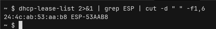
That was the AHA moment!
As per Wikipedia’s description:
The ESP8266 is a low-cost Wi-Fi microchip, with built-in TCP/IP networking software, and microcontroller capability, produced by Espressif Systems
It makes sense. To keep the hardware cost very low, they used a very cheap microcontroller with WiFi connectivity and to compensate for that, they delegated all the main functionalities like leave tracker, timesheet, etc. to a remote API.
I decided to open the device and take a look at it:
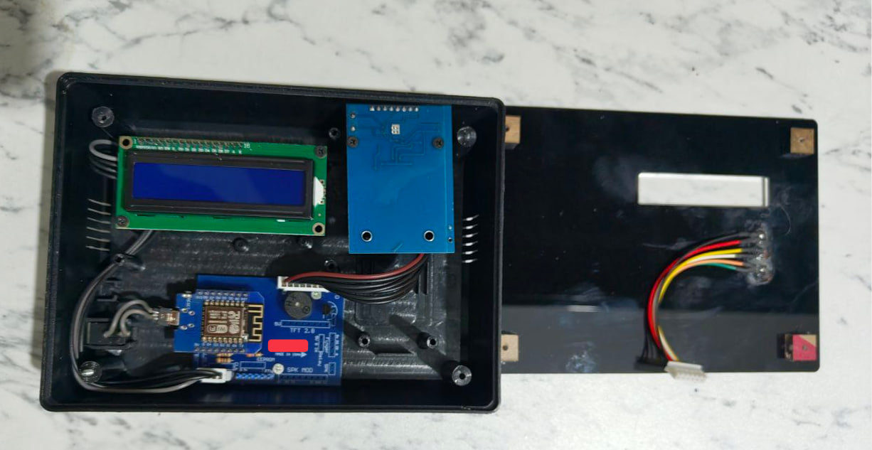
To be honest, I felt down a bit. The hardware is far from an intricate device and more like a hobby project.
Let’s review:
- Microcontroller: Wemos D1 Mini -> an ESP8266-based development board.
- Display: 1602 LCD with I2C Backpack
- RFID Reader: RC522 (MFRC522) - datasheet
- Base Board: Custom “Shield” / Carrier PCB -> Acts as a “motherboard” to fix the messy jumper wires issue. It breaks out the pins from Wemos D1 Mini to the specific headers for the RFID and LCD.
- LED Indicators
I decided to focus on the firmware instead of hardware and go as deep as possible.
Getting the Firmware
We can easily see the mini USB port that’s connected to an AC socket to act as the power source.
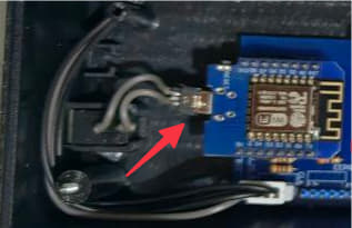
We can connect the Wemos to our PC using a simple mini USB cable, and the dumping part would be a piece of cake for these reasons:
- Hardware Disabling: You cannot disable the port via software. You must physically destroy the UART traces (TX/RX lines) or remove the USB-to-Serial IC (e.g.,
CH340) after flashing. - Flash Encryption: The ESP8266 does not support hardware flash encryption. If someone has physical access, they can bypass the USB port and wire directly to the SPI flash chip pins to dump data.
- eFuse Limitations: Unlike the ESP32, the ESP8266 lacks the
flash_crypt_cntorJTAG_DISABLEeFuses. - Physical Protection: The only real protection is potting the board in epoxy to prevent physical probing of the flash memory chip. Which in this case, they didn’t!
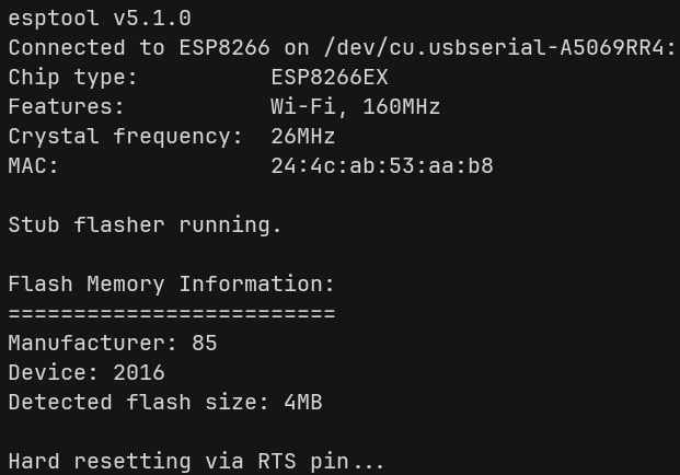
To verify my guess, I connected the microcontroller to my PC and checked the flash-id
esptool --port /dev/cu.usbserial-A5069RR4 flash-id
To Dump it:
esptool --port /dev/cu.usbserial-A5069RR4 read-flash 0 0x400000 wemos_firmware_dump.bin
Note: Wemos D1 Mini has exactly 4MB of memory, so we read it all.
And finally to verify the dump:
esptool --chip esp8266 image-info wemos_firmware_dump.bin
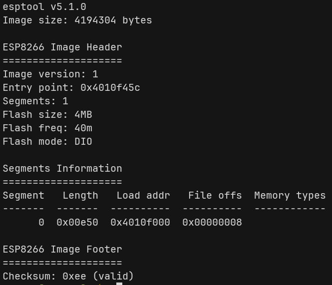
Cool, we got the entire (probably) unencrypted firmware. Let’s move to the next part!
Reading the Binary
I found this guide that describes ESP8266’s processor architecture like this:
The ESP8266 has an Xtensa lx106 processor at its core. This is a 32 bit RISC processor with 16 registers.
In the previous step we used esptool to analyze the image info. So obviously, esptool knows how to parse the image.
I digged a little bit deeper in the esptool source code and found this bin_image.py file which is responsible to parse the headers.
By looking at the file I found these headers:
- Common Header:
magic, segments, self.flash_mode, self.flash_size_freq, self.entrypoint = struct.unpack("<BBBBI", load_file.read(8))
Which is equivalent to:
struct header {
    u8  magic;
    u8  segments; // count
    u8  flash_mode;
    u8  flash_size_freq;
    u32 entrypoint;
};
- Segment Header:
(offset, size) = struct.unpack("<II", f.read(8))
Which is equivalent to:
struct segment_header {
    u32 offset; // load address
    u32 size;
};
And for the segments, data comes right after the segment header so we can write it like:
struct segment_header {
    u32 offset;
    u32 size;
    u8  data[size];
};
I dug way deeper and wrote a pattern file for the entire image with some helper variables for ImHex and sent a pull request (PR #492) for it. At this moment the PR is still open.
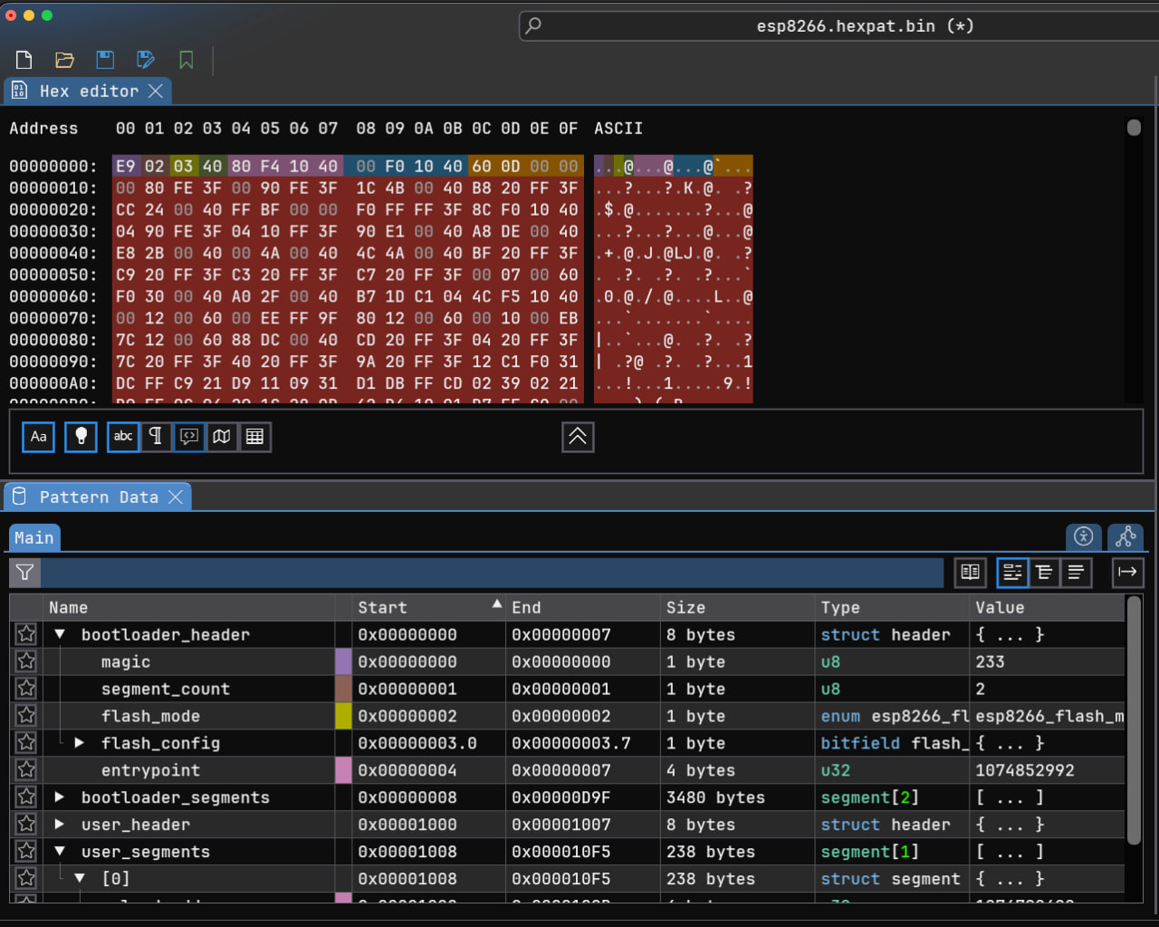
After verifying everything about the legitimacy of the firmware and writing a pattern file for it, we are ready to load it in Ghidra for further analysis.
Into Ghidra
Ghidra already supports Xtensa pretty well (added in version 11.0) and can disassemble and generate pseudocode for these processors easily. The issue resides with the custom proprietary firmware format of ESP8266. Ghidra must know where to look, where to disassemble as code, and where to look for data. For these kinds of situations, Ghidra uses loaders.
Ghidra doesn’t have a native loader that understands ESP8266 firmware. Unlike standard formats like ELF or Mach-O, ESP8266 uses a proprietary binary format with a custom header structure featuring:
- An 8-byte header with magic byte (
0xe9) for identification - Segment-based layout where each section has its own offset and size
- Multiple headers including a user ROM header at offset
0x1000 - Specific memory mappings for IROM, user code, and data segments
Without a proper loader, Ghidra would need you to manually extract and position each binary segment into the correct memory regions. The loader handles all this automatically by parsing the firmware structure and creating properly mapped memory blocks with correct permissions.
I found an older ESP8266 loader here!, but the codebase was outdated and needed updates. So I decided to send a pull request (PR #6) to contribute the fixes back to the community.
After installing and enabling the custom loader, we can easily import the dumped firmware into Ghidra:
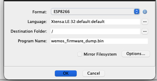
Loader parses the firmware headers like what we did in the previous sections, then creates memory layouts and fixes the permissions:
| Address | Name | Loader Section Name – | Size | Description |
|---|---|---|---|---|
| 0x3FFE8000 | dram0 | .user_data |
14000h | User data RAM. Available to applications |
| 0x40100000 | iram1 | .user_code |
8000h | Instruction RAM. Used by bootloader |
| 0x40200000 | SPI Flash | code |
- | SPI Flash is mapped here |
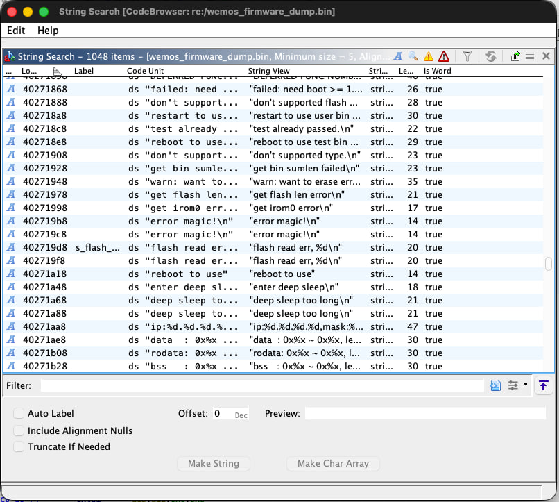
After loading the firmware into Ghidra, we can see that it was able to analyze the firmware. One of the simplest ways to verify this is by looking at the strings. Seeing meaningful strings usually means that the loader did its job and was able to map the data sections to the correct memory addresses.
If we head to the function lists, we can spot the other issue. Ghidra was unable to find function signatures using their signature db and all of the functions are labeled like FUN_*.
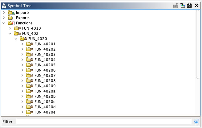
To solve this issue we can use a FidDb. It’s a database file used by Ghidra’s Function ID (FID) analyzer to identify and match functions across different binaries.
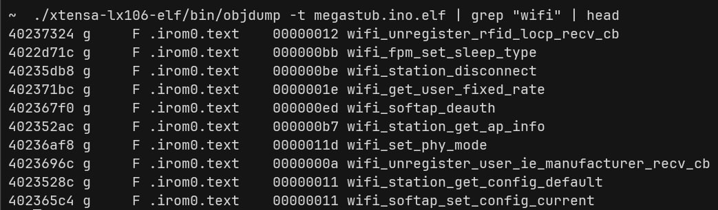
Because we are in microcontroller land, usually we are limited in terms of public FidDbs. For that reason, we need to create one ourselves.
To do that, we need to compile another firmware that uses same SDK and libraries with debug symbols on. To build a firmware for an ESP8266, there are two viable options:
- Arduino IDE + ESP8266 SDK
- PlatformIO + ESP8266 SDK
We can have an educated guess and based on the hardware design, guess that they used Arduino IDE to develop the firmware because it is much easier and user friendly.
- You can read about installing ESP8266 SDK for Arduino IDE here!
Generating function signatures heavily depends on the SDK and library version. Even minor version differences can affect function signatures due to compiler optimizations or code changes. While ESP8266 SDKs share core functionality across versions, you shouldn’t assume signature compatibility. To be honest, you cannot expect 100% function signature coverage. FidDb is a helper utility to make the reversing process easier, not an ultimate solution. That’s why I decided not to play the cat-and-mouse game. of hunting down the exact SDK version to match the FidDb perfectly. The reality is that even with a perfectly matched FidDb, there will always be functions that need manual analysis. Since ESP8266 firmware is relatively small and the FidDb provides useful partial matches even across versions, I chose to just use what’s available and move forward with the actual reverse engineering. The time spent hunting for the exact SDK version is better spent on the analysis itself.
I created this simple sketch:
#include <ESP8266WiFi.h>
#include <ESP8266WebServer.h>
#include <ESP8266HTTPClient.h>
#include <ESP8266mDNS.h>
#include <WiFiClient.h>
#include <WiFiUdp.h>
#include <DNSServer.h>

void mega_stub() {

  // Never execute
  if (false) mega_stub();
}

void setup() {}
void loop() {}
Exporting it generates two files: .bin and .elf. We need to load the .elf one because it has the debug symbols.
I then loaded it in Ghidra, let Ghidra analyze it, and generated a FidDb out of it.
Steps:
- Create an empty FidDb: Tools -> Function ID -> Create new empty FidDb
- Populate the FidDb: Tools -> Function ID -> Populate Fid Database (Use Xtensa Little Endian for the language field)
After that, we can head to the dumped firmware and attached the created FidDb (Tools -> Function ID -> Attach existing FidDb). Make sure to let the Ghidra to analyze it again!
Tadaaa!
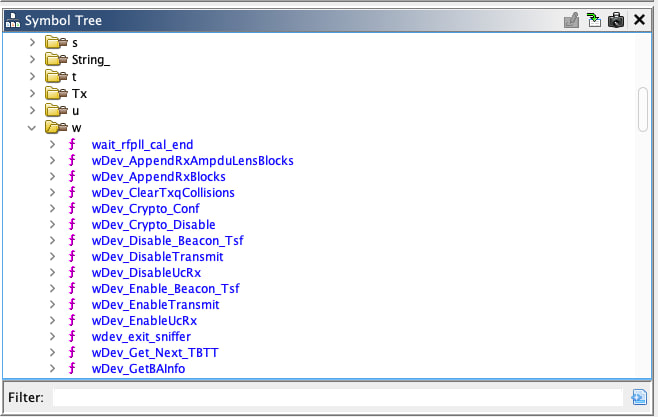
With meaningful function names now identified, Ghidra can show us the actual structure of the firmware. Instead of cryptic FUN_40200000 addresses, we now see recognizable functions like setup(), loop(), WiFi_init(), and others.
Everything is ready for our adventure.
What’s Next
In Part 1, we identified the hardware, successfully dumped the firmware and made some helper utilities along the way. We created a pattern for ImHex, and were able to load the firmware in Ghidra and adjust it so we can reverse it later with more ease.
I think we are at a good point now and ready to take the next step. In the next post (that hopefully I can allocate some time to write soon), we will take a look at the actual firmware to see how it actually works, if there are any vulnerabilities with it and what hidden functionalities exist. We will talk about ESP8266 firmware much deeper.
Feel free to ping me if you had any questions! Peace!
